QFH Antenna for Receiving Satellite Images Using RTL-SDR

There is an incredibly popular low-cost software defined radio, known as the RTL-SDR. I’ve had one of these for months, and haven’t really done anything cool with it. Recently I’ve seen a lot of people on the rtl-sdr reddit building quadrifilar helix (QFH) antennas to receive images from satellites using automatic picture transmission (APT). I decided to try this over spring break.
Step one is research. This is a pretty old ham radio project and now a lot of people are redoing it with the RTL-SDR, so there is a lot of information out there. I probably used this blog post the most, because it has links to a ton of other helpful posts.
Step two is buying materials. I bought 1" and 0.75" PVC, but if I was going to do this again I would probably buy 1.5" and 0.5". I already had copper pipe from a very old project to use for this antenna.
Then generate the template using this website. The default values for 137.5 MHz are good. Put the diameter of the conductor, which was 5mm for me. Then just scroll down and insert the two PVC diameters in mm. I measured 1" as 35mm and 0.75" as 25mm (although I know 1 inch is 25mm when converted directly) using a tape measured that had cm on it, but your pipe may be different. Download the template and print it out, but make sure the printer doesn’t scale it. Compare the printed size to your PVC to check.
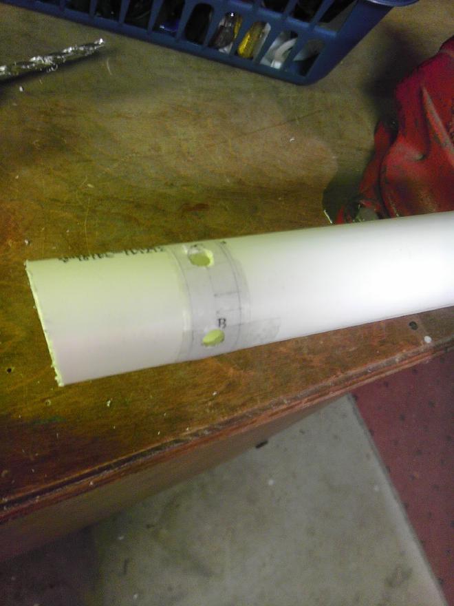
Cut out the template, tape it to your pipe, and get drilling. I had a cm measuring tape, but you might have to convert the measurements to inches if you don’t. A useful tip from here is to use a door jamb to make a line down the pipe.
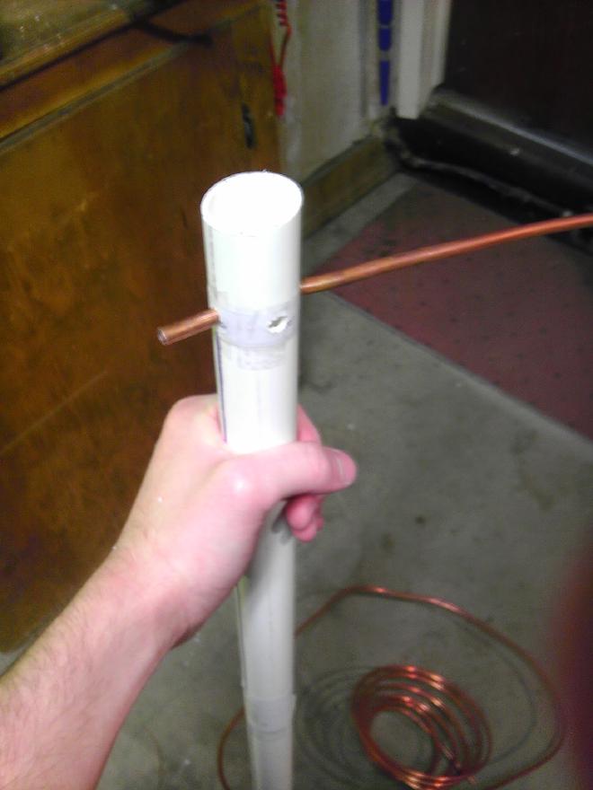
The copper pipe that I used is easy* enough to bend, but some guides say to use a log to bend the pipe if you can’t. Follow the template exactly, with pipe from hole A going to A, and D to D, etc. You should be aware that the larger loop from the template is holes B and D, which makes the smaller loop holes A and C.
*This pipe might have been too easy to bend. I had a serious kink on the bottom loop.
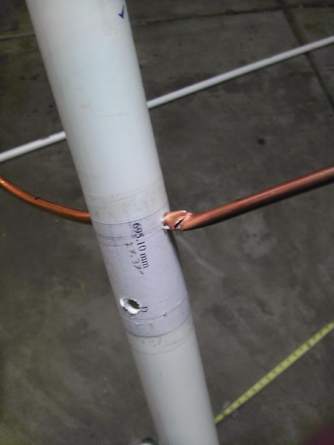
Later I tried to fix it with solder, but I don’t really think that did the job.
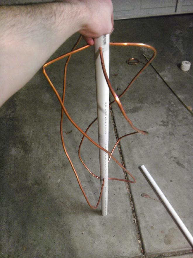
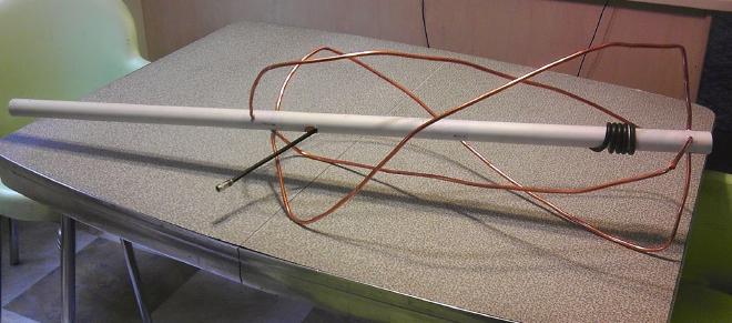
Eventually you should have something that looks weird from any direction but is generally symmetrical. Time to attach the coax.
I went through my pile of coax and picked the highest-quality, stiffest coax. This is probably overkill. Then you drill a hole near the top, feed to coax in, and solder it on. I was very confused about which wires go to which loop until I found this post, which has a nice graphic.
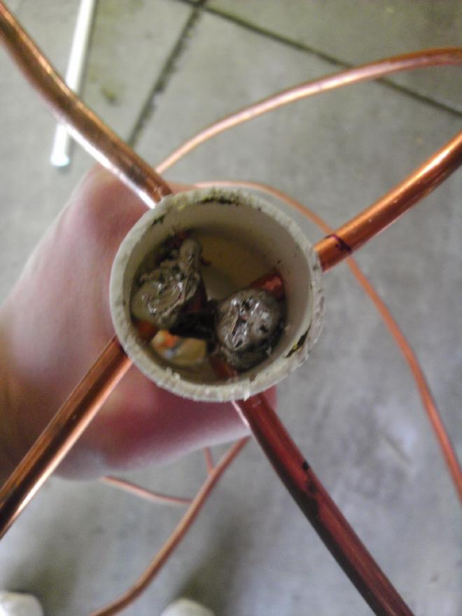
My soldering solution was an old iron set to max temp with a huge tip, and a ton of solder. Cut down the top of the pipe if you can’t reach in enough. The real tip here is to sand the copper before you solder it. Sand even if you are just using copper wire.
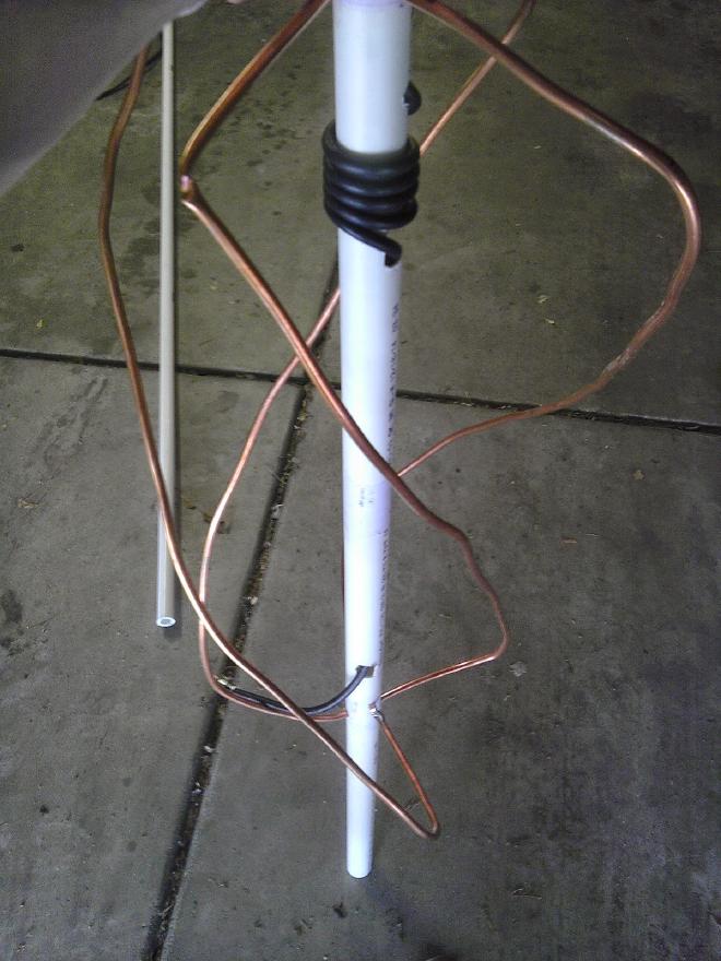
Wrap the cable tightly around the main tube a few times to create a balun. I used five times.
Later I used a piece of particle board to create a simple stand for it, but don’t have any pictures. If you have any experience with wood you can probably build one better than mine.

My RTL-SDR (in the altoids can in the picture) already has an F connector, so I just plugged it in. Then I used a usb extension cable to provide distance from the antenna. Then I waited for satellites.
To receive the images I referenced this post and used SDR#, VB-Cable and WXtoImg on Windows. It should be possible using Gqrx on Linux, but I’m sure how to pipe audio from one program to another.
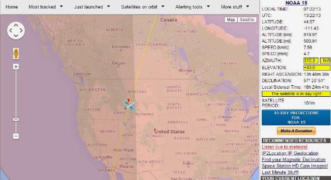
Once I had that set up I used the WXtoImg satellite pass tracker and n2yo to track NOAA 15, 18, and 19, and found that the next pass was NOAA 15 at 6am.
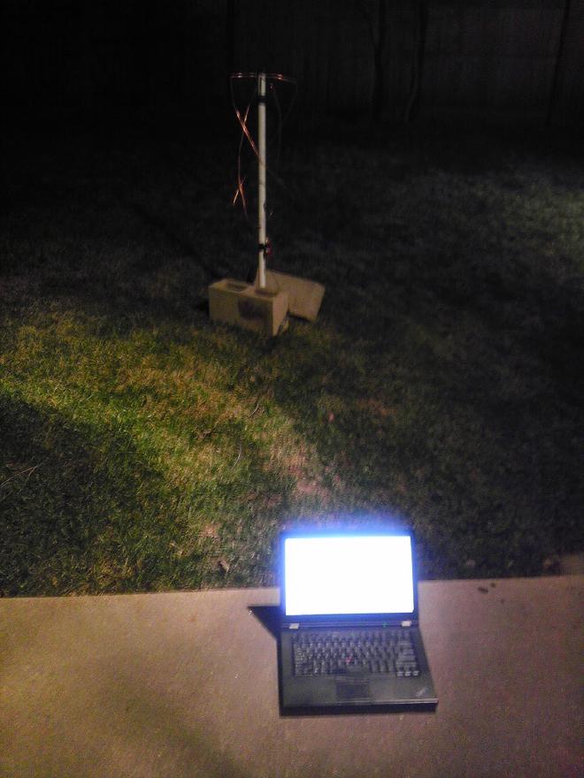
The next morning, I went out and set up and got an image! It was pretty overcast at the time, but it still worked.
After it passed I let WXtoImg decode it and got something.
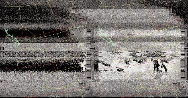
Not exactly the highest quality, but it’s there!
A few more satellites passed over that day, and I grabbed them.


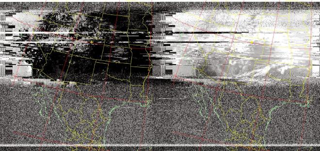
NOAA 18 and 19 had strange interference in their frequency, so the pictures really suffered. However, the idea worked.
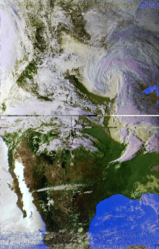
Next morning NOAA 15 was flying almost directly over me, so I went out at 6am again to get a really nice picture.
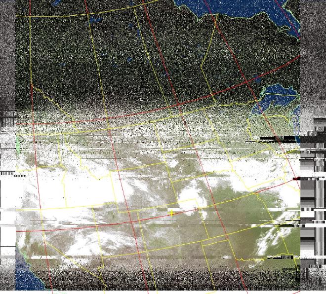
This time I was even able to do color!
Later that night I tried to record the Russian Meteor-M N2, but the signal wasn’t strong enough.
I still wasn’t satisfied, and identified some problems in the original antenna that could be improved on. Then I went to go build another antenna.
Copper pipe turned out to be pretty hard for me to work with, so I switched to 12 gauge copper wiring instead. I also used the center supporting pipes this time, and triple-checked every measurement on the antenna.
The new antenna doesn’t look as cool because there isn’t any copper showing, but it works great!
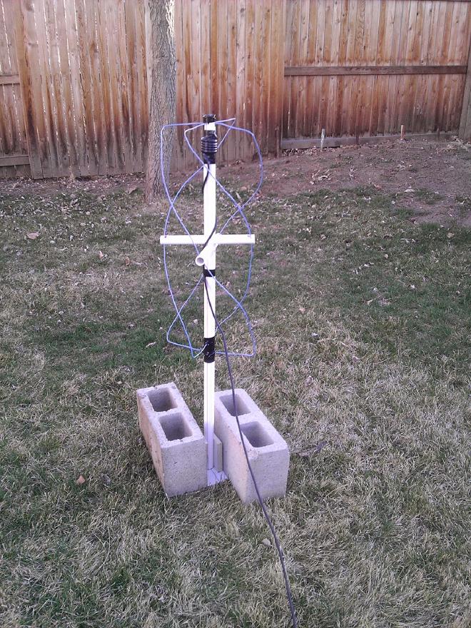
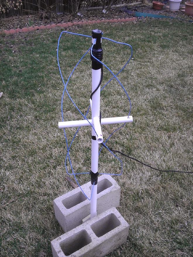
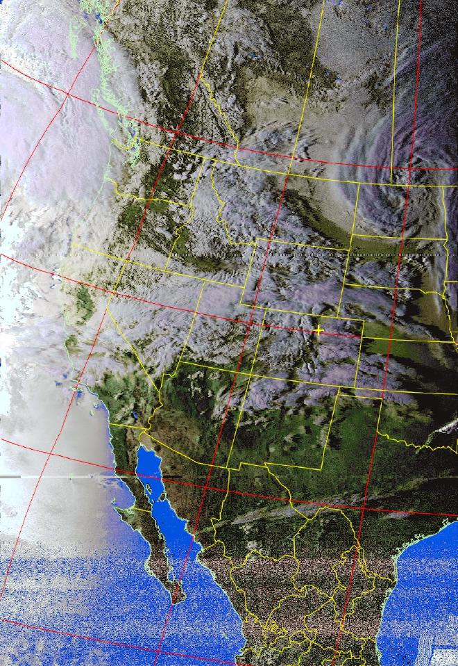
I used it to get this picture from NOAA 18, which didn’t even fly that close to me.
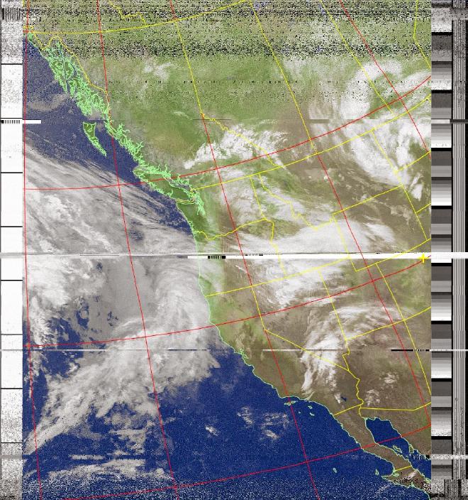
The only weird thing is that band in the middle, which I think was caused by me doing something on the computer at the wrong time.
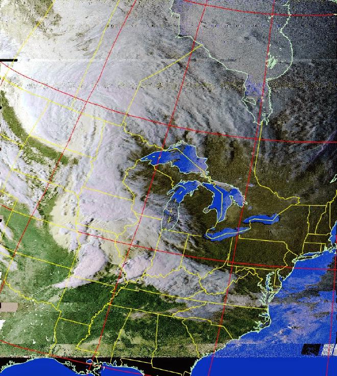
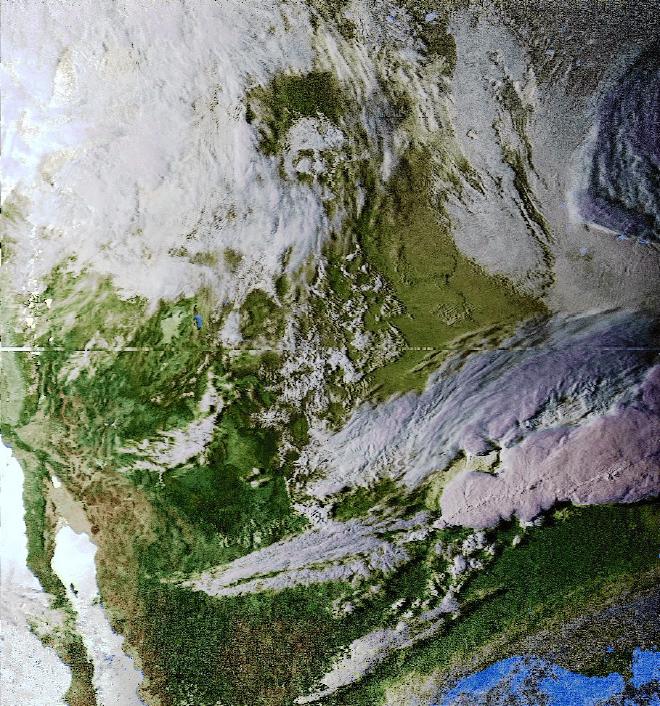
I found the best setup for me is WFM mode with a 40k bandwidth. I’m not sure how much sample rate matters, I’ve gotten images 2.8MSPS sample rate and 0.25MSPS sample rate.
With this new setup, I’ve gotten some great images.
Comments: #
Great work! I have a question about the new antenn… #
Unknown -
Great work! I have a question about the new antenna you built specifically the bottom part. Are the 12 gauge copper wires soldered together? Is it one piece?
#### It's two long wires, soldered together at the ... [Paul Schow](https://www.blogger.com/profile/02139879554145337777 "noreply@blogger.com") -
It’s two long wires, soldered together at the top. At the bottom they just run straight through.